I’ve had a handful of people asking me for a good set of intstruction on how to install the Sega Saturn mod chips
I’m not responsible for any damage you may do to your Saturn by performing this modification. There isn’t much to worry about, but I just don’t want anybody mad at me 🙂
Thanks to Jess Ragan for his help in creating this guide!
What You Need
A model 2 (32-pin – usually round-buttoned) Saturn
Phillips head screwdriver with a long thin neck that can reach the Saturn’s case screws.
A copy of a Saturn game for testing purposes.
A nail file or something similar (may only need this if chip does not fit snugly)
Step 1 – Preparation
Keep your chip safe by leaving it in the anti-static bag that I ship them in.
Unplug your Saturn
Turn your Saturn upside down on a table
Remove the Saturn’s case screws
Put the screws in a safe place
Turn the Saturn right side up.
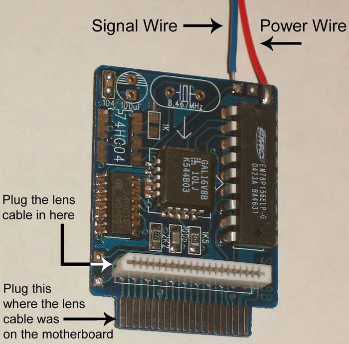
Step 2 – Install Chip and Hook-up Lens Cable
Look at the twisted white ribbon cable running from the center of the system to the shiny metal box on the right hand side.
Part of the ribbon will be taped to this metal box.
First peel the tape off the metal box, then gently unplug the right end of the ribbon cable.
Take this end of the cable and plug it into the connector on the modchip as pointed out below.
Plug the chip itself into the plug where the lens cable was.
If the chip does not plug in easily, you may need to file down the side edges of the plug in order to give it a better fit. However, you shouldn’t put too much pressure on the chip because it can crack easily. And a very gentle side-to-side wiggle can help insert it into the socket.
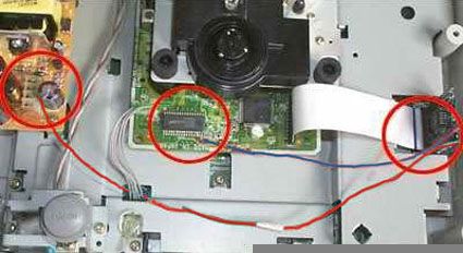
Step 3 – Getting Link Cables Layed Out
Below you can see the linking (soldering) points of the two cables from the IC chip towards the motherboad.
You can also see how the lens cable is to hooked up to the chip.
A close-up shot of both solder points follows in the next steps.
You may need to add some extra wire to extend the link cables’ reach across the machine.
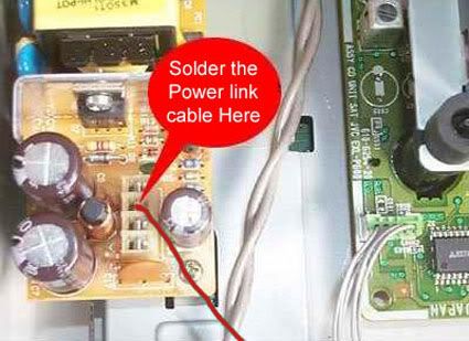
Step 4 – Connect the Power Link Cable
The small wire soldered into the left side of the mod chip is called a jumper cable
Attach this jumper cable to the Saturn to power the chip
On the left side of the Saturn, there are four metal pins in a vertical row
Take the end of the jumper cable and plug it into the second pin from the top (on the back of the unit) even if you see 5 pins instead of 4. (It’s the one marked 5VA — if one does not work, try the other).
Below is a close-up of where to solder the power cable (red)
Please note the power wire MUST solder to the power socket directly!
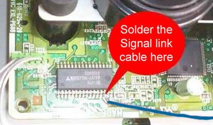
Step 5 – Connect the Signal Link Cable
There are two ways to do this step:
The original way was to solder the signal (blue) wire to pin 14 of the 32-pin chip.
To make this easier, put 2 pieces of thin cardboard surrounding and isolated the 14th pin
Then you soldered to the 14th pin very easily, ignoring the other pins
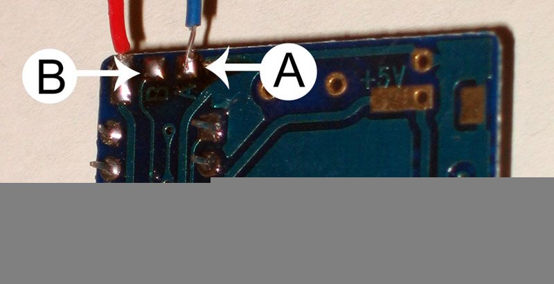
Below is close-up of where to solder the Signal cable (blue)
OR
You can get rid of the signal cable altogether and link the signal point to point B with a bit of solder instead of linking to pin 14 of the 32-pin chip.
Stick to good brand name CD-Rs and do not use CD-RWs
Burn at the slowest speed that your burner and media will allow
Check the region of the image before burning and make sure it matches the target console (use Saturn Region Patcher.)
If a burned game fails to boot but the Saturn displays the “Game disc is unsuitable for this console†message, then the burn and mod chip are working correctly but the region of the image is set to something different than the console’s region. If the console only displays audio tracks, the then the problem could be a bad image, bad burn, and/or mod chip installation issues.
When you click on links to various merchants on this site and make a purchase, this can result in this site earning a commission.
Affiliate programs and affiliations include, but are not limited to, the eBay Partner Network or Amazon Associates.
Yeah, there is quite a difference between the models and I don’t typically recommend that you even bother with modding those oval-button units.
But the chip is just for backups, but you can alter backups to change the region code.
I bought racketboy’s mod chip, which came very quickly by mail. Installation was super easy even though I’ve never soldered anything in my life. I have a model-2 64 pin NTSC US Saturn.
I removed the signal wire and soldered a bridge between points A and B then soldered the power cable to the appropriate point. I had to file the plastic of the chip down a bit to make an easy fit. At first I made the mistake of seating the chip with the optical cable connector facing the cd drive, which created the condition where no games, original or backup would be recognized. After switching the way the chip was seated it worked like a charm, although I have to open the cd lid and close again in order to get a “launch application” function to show up. All in all I am VERY pleased with the outcome, and what’s more – soldering is kinda FUN!! Thanks a bunch Racketboy!!
Hi there, Racketboy! Please update your guide using this information: http://www.segastyle.com/model264.html
It worked great on my 64-pin model 2, even though I’ve got the disc-detection bug where you have to open the lid up and close it again. No biggie.
For those who have had their chips stop working,
mine did, after ~7 years of faithful service, and i found the cause was some _very_ fine breaks in the pcb near the ribbon cable connector, I soldered a couple wires to repair the damage, and it is working fine again 🙂
Yeah, there is quite a difference between the models and I don’t typically recommend that you even bother with modding those oval-button units.
But the chip is just for backups, but you can alter backups to change the region code.
Just got my Saturn chip….super fast shipping, super easy instal (especially considering my first time using a soldering iron)…..thanks!
I bought racketboy’s mod chip, which came very quickly by mail. Installation was super easy even though I’ve never soldered anything in my life. I have a model-2 64 pin NTSC US Saturn.
I removed the signal wire and soldered a bridge between points A and B then soldered the power cable to the appropriate point. I had to file the plastic of the chip down a bit to make an easy fit. At first I made the mistake of seating the chip with the optical cable connector facing the cd drive, which created the condition where no games, original or backup would be recognized. After switching the way the chip was seated it worked like a charm, although I have to open the cd lid and close again in order to get a “launch application” function to show up. All in all I am VERY pleased with the outcome, and what’s more – soldering is kinda FUN!! Thanks a bunch Racketboy!!
Hi there, Racketboy! Please update your guide using this information:
http://www.segastyle.com/model264.html
It worked great on my 64-pin model 2, even though I’ve got the disc-detection bug where you have to open the lid up and close it again. No biggie.
For those who have had their chips stop working,
mine did, after ~7 years of faithful service, and i found the cause was some _very_ fine breaks in the pcb near the ribbon cable connector, I soldered a couple wires to repair the damage, and it is working fine again 🙂
hope this can help someone else as well!
Hi I need a mod chip for mk2 round buttons please, racketboy are you still knocking about? Thanks