Genesis Model 2 AV pins on Circuit Board

Need help with your PC or Modding Projects?
Post Reply
suprmonky73
8-bit
Posts: 24
Joined: Fri Sep 13, 2013 2:18 pm
Location: charlotte , nc

Genesis Model 2 AV pins on Circuit Board

Post by suprmonky73 »

I've found this information for the model 1, and it seems to be more prevalent because the Model 1 AV 8 pin din is uncommon. However for just tinkering with my model 2 I have not been able to find this information.

Background so you don't think I'm doing this for no reason: i have a bunch of Sony PVM monitors and rather than buying the expensive cables I'm messing with the idea of doing something similar to the regular Model 1 AV mod where you put RCA jacks on the back of the console. I'm going to put R G B and sync RCA's on the back of mine after tapping into the circuit board.... the problem I am trying to solve is which pins on the bottom of the board are which.

Here is a picture of the top and bottom of the model 2 circuit board. Lucky for me pins 4,5,7,8,9 are labelled on the top and using the pinout from GameSX's diagram I successfully tested it and pin 5 does correspond to Composite.

Image

Image

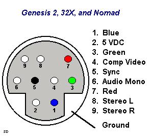
On the top of the board the top 4 pins are not labelled or they are covered by the actual female DIN moduel. Anyone know which pins are which? I'm not a soldering expert so I'd rather not poke around and either fry the system or myself :)
suprmonky73
8-bit
Posts: 24
Joined: Fri Sep 13, 2013 2:18 pm
Location: charlotte , nc

Re: Genesis Model 2 AV pins on Circuit Board

Post by suprmonky73 »

testing audio confirms pin 6 is on the top left, above the left and right stereo....makes sense that they're all next to each other.

Now to find blue and green...
User avatar
Hobie-wan
Next-Gen
Posts: 21705
Joined: Sat Aug 15, 2009 8:28 pm
Location: Under a pile of retro stuff in H-town
Contact:

Re: Genesis Model 2 AV pins on Circuit Board

Post by Hobie-wan »

Do you have a multimeter? Use that to test continuity between the solder points and the sockets in the connector.
suprmonky73
8-bit
Posts: 24
Joined: Fri Sep 13, 2013 2:18 pm
Location: charlotte , nc

Re: Genesis Model 2 AV pins on Circuit Board

Post by suprmonky73 »

never used one before, but it's probably time to invest in one. thanks!
User avatar
Ziggy
Moderator
Posts: 14913
Joined: Mon Jun 09, 2008 5:12 pm
Location: NY

Re: Genesis Model 2 AV pins on Circuit Board

Post by Ziggy »

Hobie-wan wrote:Do you have a multimeter? Use that to test continuity between the solder points and the sockets in the connector.
Yes. And if your meter's probes don't fit into the AV socket (which is likely) then use a straightened paper clip.
suprmonky73 wrote:never used one before, but it's probably time to invest in one. thanks!
I'll just put the same old info I always do about meters...

This is my recommended budget meter:

You can get a variety of similar budget meters in your local hardware and auto parts stores. It's more than worth owning one if you're into doing such things. Hell, I vote a ~$10 meter is worth owning just to check battery life.

Get a digital meter, not an analog one. Get a meter that does at least voltage and resistance. A cheap meter might not have a continuity setting, like the one I linked, but you can use a resistance setting for continuity (you just wont have an audio indicator).
Teh Lurv
24-bit
Posts: 135
Joined: Thu Jan 31, 2013 2:09 pm
Location: Boston

Re: Genesis Model 2 AV pins on Circuit Board

Post by Teh Lurv »

Since the Model 2 AV output already includes RGB pins, I say it would be easier to solder together your own custom cable rather than add additional RCA outputs to the Genesis.
suprmonky73
8-bit
Posts: 24
Joined: Fri Sep 13, 2013 2:18 pm
Location: charlotte , nc

Re: Genesis Model 2 AV pins on Circuit Board

Post by suprmonky73 »

Thanks for the posts everyone.

No multimeter yet but narrowed it down , just haven't found which is green or blue because i didn't really test.

Ended up doing this on a Model 1 where the pins were already labelled in my first post... and the pins are much larger and spread apart. So less worrying that im going to bridge two together being that I am a beginner with soldering.

For my model 2 I ended up buying a 6 foot male to male 9 Pin minidin cable (the 9b one) and cut it in half. My cable blows but it works :)
Post Reply