Okay great. Here's what I posted on shoryuken. Maybe someone here can help answer my questions and concerns as well.
Okay, so I've learned a bit more and would like some help from those in the know.
I have two possible Mayflash PS2/USB pcbs I can use - one from 2007 and one from 2009. Careful examination of them both seems to suggest that they are both common ground. The only difference between them is that the 2007 maps the joystick inputs to the PS2 dpad, whereas the 2009 model maps them to the PS2 left stick, which is a problem when using the adapter with the original Xbox running XBMC as the dash since you can't navigate the menu with the left stick, only the dpad.
If you guys would like, I can post images of all pcbs that will be involved.
I've never done a dual mod, but I DO have experience padhacking for building arcade sticks. I created a thread asking about this on racketboy and was told some interesting info. Here's what I've bee told:
"It's always been my understanding that if both PCB's accept the same voltage (i.e. both 5v or both 12v), and the common ground is connected, you need the VCC connected too, and then only plug in one at once. Yes, both boards would be powered, but only one communicating. If the other board isn't powered it's more likely to cause interference or drain power from the active board."
and also:
"The golden rule is that both PCBs need to be common ground. Afterwards, all you need to do is connect the grounds, the vcc (In this case you shouldn't worry about the voltage to your current Mayflash, it accepts +5v from USB already), as well as the corresponding signals (left to left, (360) A to (Ps2/3) X or however you want your button mapping) and go from there. You could have two cables coming out, I would highly suggest you never plug in more than one cable at a time though."
I then came across this diagram of how to dual mod a first gen PS1 controller and a wired Xbox 360 controller together
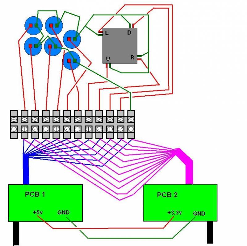
This would seem to confirm the idea that the VCC lines need to be connected, but I'm baffled by the concept that a 3.3v and 5v line should EVER been connected - would that blow the 3.3v PS1 stick?
Regardless, I don't think that I'll have to worry given that both the Mayflash and the Paewang both are the same voltage - at least to my understanding. I know the USB cord for the Mayflash pcb will of course be 5v, but I never plan to use that - only the PS2 port will ever be used.
Should I attach VCC from the PS2 cord input or the USB cord input or doesn't it matter? I'm not entirely sure what the PS2 voltage is - 3.3v, 5v or what.
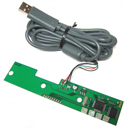
Here are images of the pcbs I will be using, labelled.
Paewang:

Mayflash (although the labeling is probably not right for the 2007 pcb I have and plan to use - the guy who posted this said it was his 2009 model)

One final question while I think of it - is there any limit (becides physical space) to the number of padhacked pcbs that could be placed in a single arcade stick? If I am successful in getting the Mayflash and Paewang together in one stick, I'd also possibly like to put an NES MAX and a RetroDuo clone SNES controller in one stick. They too are both common ground and are both 5v.
Thanks for any help!