Model 1 Sega Saturn ModChip Installation Guide
This Saturn is by far the most difficult because you need to have some skill with a soldering iron. The actual installation of the chip is quite easy once you have correctly altered the chip. Model 1 Chips are no longer in production, so unless you can find some backstock or place that has some left over this is your only alternative other than buying a model 2 system.
Tools needed:
- Sega Saturn Mod Chip
- Philips head screw driver
- Solder and Soldering Iron
- Razor or knife
- Dremel Tool (Optional use for grinding Mod bard
Step 1: Altering the ModChip.

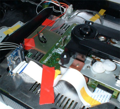
Not only does the Model 1 use 1 less conductor between the CD board and the motherboard, but some of the signals travel on different pins. This means it is necessary to re-route some of the connections on the modchip so that the correct data gets manipulated by the chip. The following images best demonstrate how to do this. Notice that in addition to re-routing the chip it is also neccessary to remove pin 21 from the modchip so that it can be seated into the motherboard of the Saturn.
Green: Traces to re-route
Red: Traces to cut
Yellow: Indicates pin 1 on the Chip
| Technical Pinout |
| Pin |
21 pin |
20 pin |
|
|
|
| 1 |
IC 20 315-5746 pin 7 [8MHz clock] pad B |
SH-1 Pin 79 logic HIGH |
| 2 |
Ground |
Ground |
| 3 |
SH-1 Pin 107 DATA/td> |
SH-1 Pin 107 Data |
| 4 |
SH-1 Pin 108 Stop packet strobe[response byte?] |
SH-1 Pin 108 Stop packet strobe[response byte?] |
| 5 |
SH-1 Pin 101 OE |
SH-1 Pin 101 OE |
| 6 |
SH-1 Pin 100 Start packet strobe[command byte?] |
SH-1 Pin 111 WR strobe |
| 7 |
Pin 111 WR strobe |
SH-1 Pin 100 Start packet strobe[command byte?] |
| 8 |
Ground |
Ground |
| 9 |
unused R48 [alternate 4MHz location diff rev.?] pad 0019 |
JP5 [8MHz clock] |
| 10 |
YGR-019B pin 123 |
Ground |
| 11 |
SH-1 Pin 79 |
YGR-019B pin 124 ??? logic low |
| 12 |
Ground |
YGR-019B pin 125 Read strobe |
| 13 |
YGR-019B pin 126 and 129 OE fetch data |
YGR-019B pin 126 OE |
| 14 |
YGR-019B pin 125 and 131 [4MHz clock] pad 0014 |
Ground |
| 15 |
XYGR-019B pin 130 CD buffer DATA |
YGR-019B pin 128 Data Read OE [?] active only during data fetch |
| 16 |
Ground |
YGR-019B pin 129 OE fetch data |
| 17 |
IC 39 VHC08 pin 2 |
YGR-019B pin 131 [4MHz clock] |
| 18 |
YGR-019B pin 122 |
YGR-019B pin 130 CD buffer DATA |
| 19 |
GR-019B pin 118 via 300 Ohm R175 |
Ground |
| 20 |
YGR-019B pin 128 |
R47 (4.7KOhm), not sure where the other side of R47 goes ATM.. |
| 21 |
YGR-019B pin 121 |
|
| Credits for this information go to Pinchy and ExCyber of Sega Xtreme |
The pins that you have to cut and reroute on the modchip are 7,13,15,18 the hardest part is transferring 15->18.
C= plastic ribbon connector (where you plug in ribbon on modchip)
E= edge connector of modchip (part of mod that connects to Saturn motherboard)
What traces to reroute:
Cut pin 7 C -> pin 6 on EM78
Connect Pin 6 EM78->pin 5 C
Cut pin 13 C -> Cap
Connect Cap-> pin 16 C
Cut pin 15 E -> pin 12 157
Cut pin 15 C -> pin 14 157
Cut pin 18 E -> pin 18 C
Connect pin 12 157 -> 18 E
Connect pin 14 157 -> 18 C
Connect pin 15 E -> pin 15 C
Remove solder from pads 0019,0014
Connect middle pad -> pin 17 C
remove solder/jumper/connection from A/B pads
Conect pad A [8MHz]-> Pin 9 C
Trim off pad 21 with dremel and you're done.
Step 2: Installing the chip.
 Assuming you have done the above step correctly the rest should be a breeze in comparison. Simply insert the chip into the motherboard and then insert the ribbon cable. For the 5v power you can splice into the red wire thats going to the power supply on the lid, for the Saturn that has the power supply on the bottom half you can connect to the im not sure yet. Assuming you have done the above step correctly the rest should be a breeze in comparison. Simply insert the chip into the motherboard and then insert the ribbon cable. For the 5v power you can splice into the red wire thats going to the power supply on the lid, for the Saturn that has the power supply on the bottom half you can connect to the im not sure yet.
Make sure you cut out any metal shielding near the modchip, you dont want it to accidentally contact something and short out! In some models of the Saturn the ribbon cable will barely reach, you can try to stretch it out a bit, or buy a longer one from digi key. You need 1mm pitch flat flex cable from and ZIF female connectors too. http://www.digikey.com/
The part numbers are:
WM10085-ND CABLE FLAT FLEX 20POS 1MM 10"
HFE20F-ND CONN FPC/FFC 20POS 1MM SMD
Credits: Credits for images, Gogou, Seal1,and GivenBack. The actual method, original guide and the 20 pin pinout was discovered by Pinchy . Original Pinout of 21 pin by Excyber and Mal.
Disclaimer: I take no responsibility for any damages or harm that you may bring to yourself or your Sega Saturn Console by making the above modifications. All laws concerning the use of these chips and the back-up games they allow you to play are to be followed and I take no responsibility for any trouble you could bring upon yourself.
|

