Page 1 of 1
Sega Genesis: RGB with 8 DIN Straight to BNC
Posted: Thu Nov 06, 2014 2:30 am
by Oceanrhode
I'm starting the pilgrimage to RGB, and am doing it on a Sega Genesis Version 1. There are some Cables that go from the 8 pin to SCART, then you need a SCART to BNC to get into an RGB monitor, (Like the Sony PMV, I plan to use).
Either way, I'm proficient in soldering and DIY, but do not know the pin requirements for RGB audio. Looking at the 8 pins at the back here:
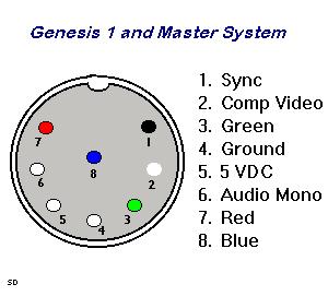
Can i just wire an 8 pin DIN with 4 BNC's and use the red, green, blue, plus SYNC signal? Concerens I have are if that ground is a common ground between all signals, and if the 5v is used for anything.
Can anyone tell me if this idea will work? or any concerns I should be aware about? Thanks all.
Re: Sega Genesis: RGB with 8 DIN Straight to BNC
Posted: Thu Nov 06, 2014 3:16 am
by theclaw
Re: Sega Genesis: RGB with 8 DIN Straight to BNC
Posted: Thu Nov 06, 2014 3:45 am
by KalessinDB
In other news,
GameSX has about every pinout you're ever likely to need.
Re: Sega Genesis: RGB with 8 DIN Straight to BNC
Posted: Thu Nov 06, 2014 11:50 am
by Oceanrhode
I think I found the easiest way to do this without the expensive SCART cables. I can't find any literature on that 5v pin doing anything for video, so I'm assuming its not used. The ground pin is used for all the shielding (I'd think) so that would be a pain to solder from a DIN to 4 BNC's so the solution is of course already been done, which is to wire the DIN to a VGA and buy the relatively cheap VGA (HD15) to BNC cables. A also found this diagram of those cables:
I'll wire "pin 4"
from the DIN to pin 6 or 4 on the VGA.
Only worrysome thing is on retroRGB.com they say take note of the ground, but on gamesx, his custom wiring doesnt have a pin for ground. So I'm confused on that discrepency.
http://www.gamesx.com/misctech/mypin.htmWhy doesn't he use a ground pin?
Re: Sega Genesis: RGB with 8 DIN Straight to BNC
Posted: Sat Nov 08, 2014 2:34 am
by ApolloBoy
Oceanrhode wrote:Why doesn't he use a ground pin?
On his connector, the shroud of the D-sub connector acts as ground.
Re: Sega Genesis: RGB with 8 DIN Straight to BNC
Posted: Sat Dec 20, 2014 2:38 pm
by Teh Lurv
IIRC the +5v pin is used by SCART cables to signal to the input RGB is being carried, otherwise the input defaults to the composite signal.
Re: Sega Genesis: RGB with 8 DIN Straight to BNC
Posted: Sat Dec 20, 2014 2:56 pm
by Ziggy
The +5v is used by RF adapters (to power them).
edit: These are all standard off-the-shelf connectors, so making a cable is easy. Get an 8-pin DIN male plug (not sure if
this is the exact one you need). You can get BNC connectors too, but I don't know if they'd be a pain in the ass to solder or not. What I would do is get a
component cable and cut the RCA plugs off one end, then wire that end to the DIN connector. Then I would get
RCA to BNC adapters for the RCA end to use on the PVM. Then I'd get a composite AV cable and do the same, using yellow for sync and then white and red for audio (for the model 1 Genesis you'll need a 3.5mm plug for stereo audio - the rear multi AV out only supplies mono). It'd be perfectly functional. And since it's RCA cables, they'll all be shielded too.
Just tie all the cable shields together and then to the ground pin on the DIN connector. Those AmazonBasics component cables are pretty nice (I have one) but they have thick jackets. You wouldn't be able to stuff all 3, plus another wire for sync, into a DIN plug. What I would do is use a ~6" piece of shielded CAT5 or CAT6 cable, that'll fit into the DIN plug nicely. Then use some heatshrink tubing to make it look nice, if you must.