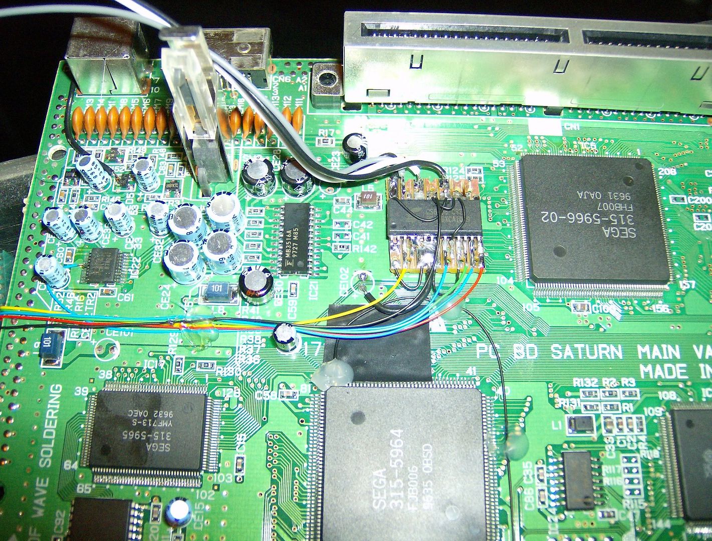
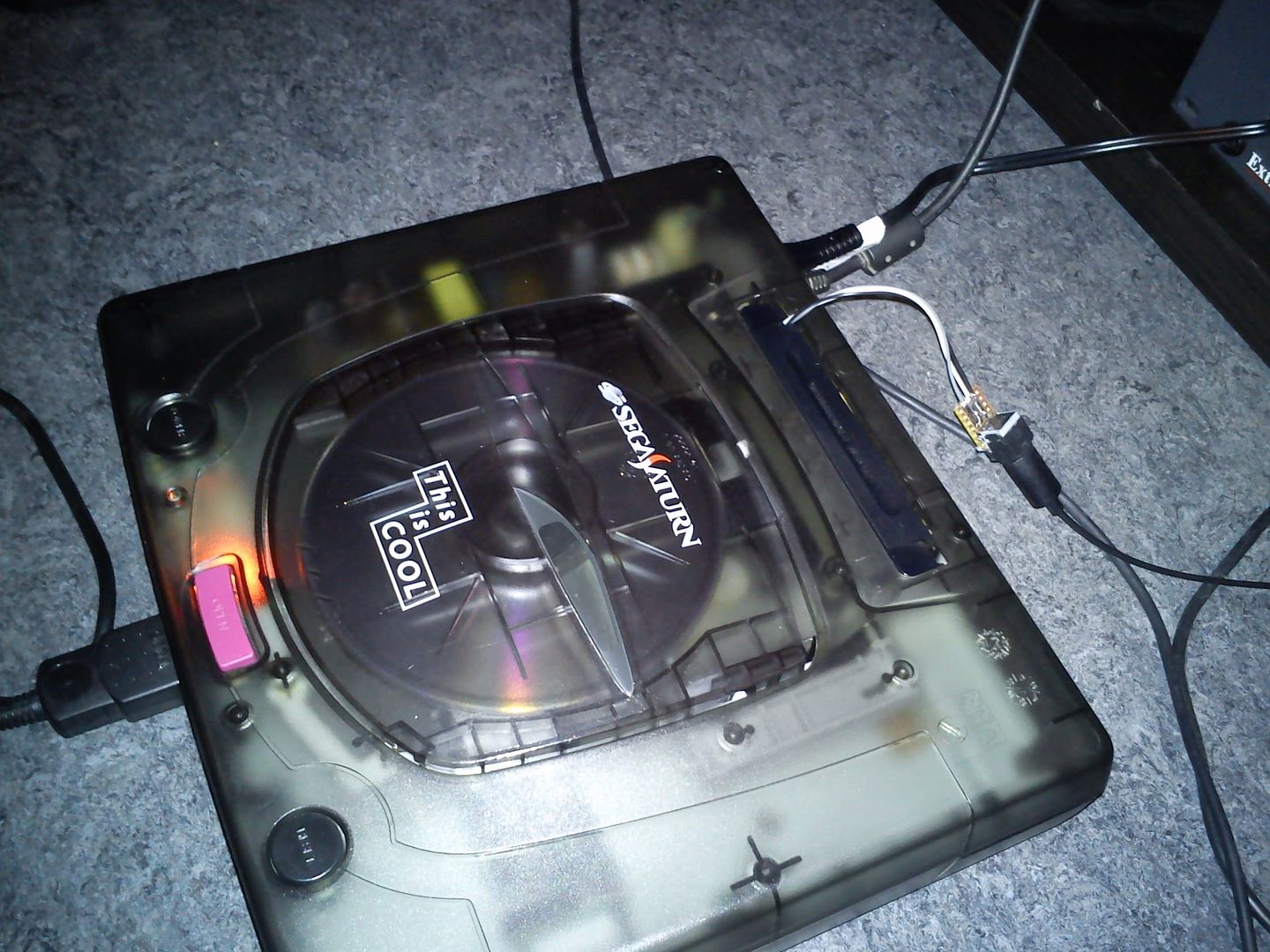
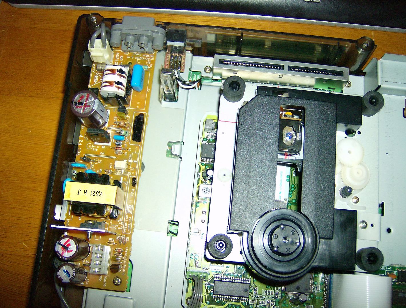
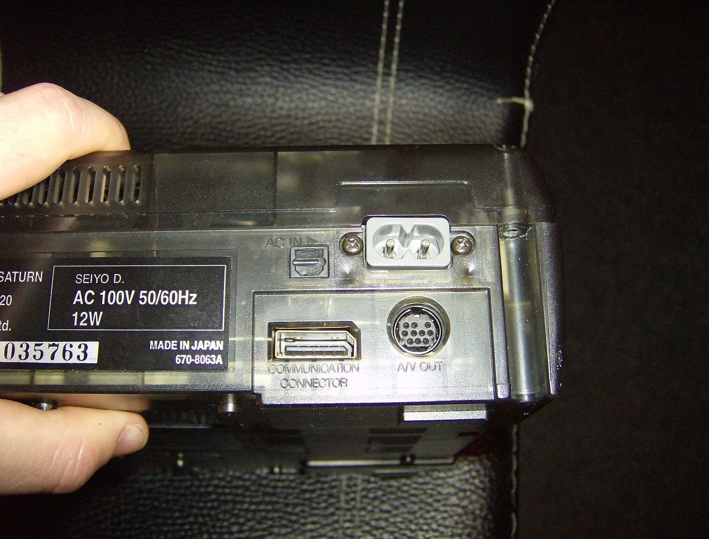
*Update2* SPDIF Audio mod Sega Saturn with *ahem* big pics

Discuss all hardware and software modifications
User avatar
Konsolkongen
Newbie
Posts: 10
Joined: Sun Dec 04, 2011 6:55 am

Re: *Update2* SPDIF Audio mod Sega Saturn with *ahem* big pi

Post by Konsolkongen »

I got this up and running with toslink cables on a Japanese VA13 Saturn. The DAC is a newer type than the ones mentioned on GamesX, but since it shared the same "TP"-points on the bottom of the motherboard it was fairly simple to figure out.
No inverter needed for this model :)

I only took very few pictures of the process, but I will try to draw up something that explains in detail how to perform this mod on a VA13 Saturn. It won't happen 'till after Christmas though :/

In the meantime:
http://i40.photobucket.com/albums/e236/ ... IM0255.jpg
http://i40.photobucket.com/albums/e236/ ... C00105.jpg
brendanraymond
24-bit
Posts: 169
Joined: Thu Mar 04, 2010 1:18 am

Re: *Update2* SPDIF Audio mod Sega Saturn with *ahem* big pi

Post by brendanraymond »

Wow you did a very neat job. I like where you placed the toslink led transmitter... I should put mine there too :)

Sorry for the late reply, but I've been abit sick. But in regards to lifting the pins (not stated on that website I linked) is because one of the three data wires is bidirectional, and I think this is for checksum or something... so to avoid any interfearance I wired them to a switch so that only one DAC would be connected at one time. I was just being over cautious... it probably works fine with them both connected anyway.

Also, do you know much about modifying xrgb3?
User avatar
Konsolkongen
Newbie
Posts: 10
Joined: Sun Dec 04, 2011 6:55 am

Re: *Update2* SPDIF Audio mod Sega Saturn with *ahem* big pi

Post by Konsolkongen »

Lol, it was just a test to see if it worked before I started cutting in the skeleton case :D For region I have installed a new Bios and 50/60Hz is done with the reset button.

Here are a few more pics I took the day after, when I made the hole for the toslink transmitter. I think it turned out pretty good:
http://i40.photobucket.com/albums/e236/ ... IM0256.jpg
http://i40.photobucket.com/albums/e236/ ... IM0259.jpg

As for lifting the pins, I understand why you did it, but the DAC in mine is so incredibly small and lifting the tiny pins would be almost impossible. Thankfully the analog audio sounds the same after doing this mod.

What mods on the XRGB-3 are you thinking about? I have modified the RGB (GAME-IN) input on mine to use EU Scart cables rather than the Japanese RGB21 standard. I added 3 220uF caps on the D1 (component) input in the back to remove most of the noise in the PS2's component video signal.
I also replaced the Panasonic video splitter chip when it died in mine (no video :(), but I wouldn't recommend that unless yours is dead ;)
brendanraymond
24-bit
Posts: 169
Joined: Thu Mar 04, 2010 1:18 am

Re: *Update2* SPDIF Audio mod Sega Saturn with *ahem* big pi

Post by brendanraymond »

I'd give you a 10/10 for neatness!

As for the xrgb, I've been having trouble trying to standardise all of my rgb signals from my consoles. From memory (about 6 months ago) I was using the vga port on the back as it takes 15khz rgb... but the pain in the butt issue is that on some consoles, composit video works well for sync, and some some consols have to use the standard sync line... but they seem abit noisy or something... so I was wondering how to work out how to put caps on the rgbs lines or build sync splitters etc... I'm not really sure exactly is the problem as every console is differrent.
User avatar
Konsolkongen
Newbie
Posts: 10
Joined: Sun Dec 04, 2011 6:55 am

Re: *Update2* SPDIF Audio mod Sega Saturn with *ahem* big pi

Post by Konsolkongen »

I use c.sync on all my consoles (Saturn, MegaDrive 1 and SNES) since it's my experience that you might get dropouts every now and then, if you use composite video as sync, especially when the screen flashes white.

I did have some trouble using c.sync on this VA13 Saturn. For some reason this was what it looked like when I connected it to either the XRGB-3 or TV directly:
Image

After a bit of experimenting various solutions I found that all that was needed was a 220uF capacitor on the c.sync line. Now it looks great :)

But about the noise. Are you using LPF? If I turn OFF LPF when using this particular Saturn I get horrible "jailbars" in the picture, and if I have it ON it looks fine. Do you also get noise when using the GAME-IN port in front? The first RGB to VGA cable I made wasn't grounded properly so I got a bit of noise when using the VGA port in the back too. The one I'm using now looks every bit as good as the GAME-IN.

I don't think you need a sync splitter when using c.sync. If your console only does composite video as sync then using a sync splitter might cure the occasional dropouts.
I haven't used a sync splitter in a long time, but when I did use composite video on my MegaDrive it worked pretty well. I build one myself using this information:
http://www.gamesx.com/misctech/lm1881.htm

Alternatively you could buy a Sync Strike from here:
http://wp1114205.wp150.webpack.hosteuro ... ucts_id=15

I don't know if it does anything different from the one you can build yourself, but besides the sync splitter feature it would serve well as a RGB to VGA adapter for your XRGB-3. Just keep in mind that this is wired to the European SCART standard.
User avatar
SGGG2
24-bit
Posts: 117
Joined: Mon Jan 04, 2010 11:29 am

Re: *Update2* SPDIF Audio mod Sega Saturn with *ahem* big pi

Post by SGGG2 »

That pic looks familiar. :wink:

What size caps did you get? I ordered some off ebay and they were way too big.
User avatar
Konsolkongen
Newbie
Posts: 10
Joined: Sun Dec 04, 2011 6:55 am

Re: *Update2* SPDIF Audio mod Sega Saturn with *ahem* big pi

Post by Konsolkongen »

Haha, hope you don't mind ;)

220uF.

I have since then compared schematics from the VA0.5 and VA13 Saturn. Of course many things differ, but video out part was somewhat identical, and on the VA13 it lacks a 75ohm resistor and 220uF cap. Seems like the 220uF cap is good enough on it's own though.
User avatar
SGGG2
24-bit
Posts: 117
Joined: Mon Jan 04, 2010 11:29 am

Re: *Update2* SPDIF Audio mod Sega Saturn with *ahem* big pi

Post by SGGG2 »

by size I meant millimeters... :lol:
User avatar
Konsolkongen
Newbie
Posts: 10
Joined: Sun Dec 04, 2011 6:55 am

Re: *Update2* SPDIF Audio mod Sega Saturn with *ahem* big pi

Post by Konsolkongen »

Ah of course. Sorry but the one I used was one I pulled from an old MegaDrive 1 I did some modifications to. Didn't buy it :/
I just installed it in the cable, there's plenty of room in the Scart socket.
User avatar
Konsolkongen
Newbie
Posts: 10
Joined: Sun Dec 04, 2011 6:55 am

Re: *Update2* SPDIF Audio mod Sega Saturn with *ahem* big pi

Post by Konsolkongen »

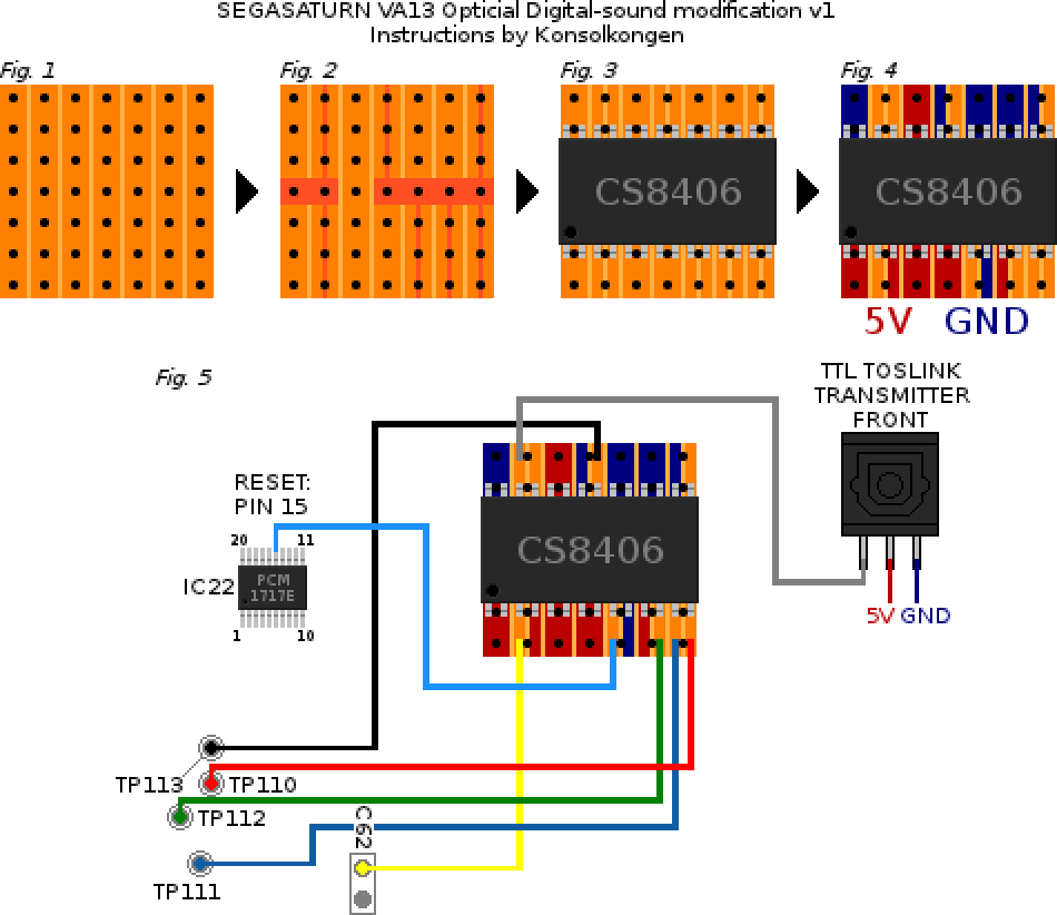
As promised I have tried to draw up instructions to do this mod on a VA13 Saturn. It might partially match other Model 2's as well, but the DAC might be different, and therefore the Reset line goes somewhere else.
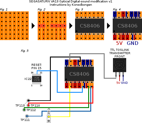
Image
2X zoom, click here: http://i40.photobucket.com/albums/e236/ ... inkmod.png

I'll try to explain it as simple as possible. You'll need a CS8406 IC and a Toslink transmitter (see the gamesx wiki for info on coaxial-output).

Fig. 1: Cut a stripboard to 7x7 holes
Fig. 2: Break the traces as shown. Use a power drill for large areas, and a sharp blade to split the traces. Make sure there is NO connection, so use a continuity tester when finished.
Fig. 3: Solder the CS8406 to the stripboard. Be sure that the chip is facing the right way (the dot indicates leg 1).
Fig. 4: All red areas must be connected to 5V and all blue to GND. There are plenty of 5V and GND points located on the motherboard (MB).
Fig. 5: Glue the board unto the MB and solder wires as shown. The Reset wire is the most tricky one, as the leg on the PCM1717E DAC is tiny, so I would highly recommend using kynar and liquid flux here. The C62 and TP-points are located on the underside of the MB. The signal wire connects to the left pin of the Toslink transmitter, looking at the front. Center is 5V and right is GND, I connected these to the red and blue areas on the stripboard.

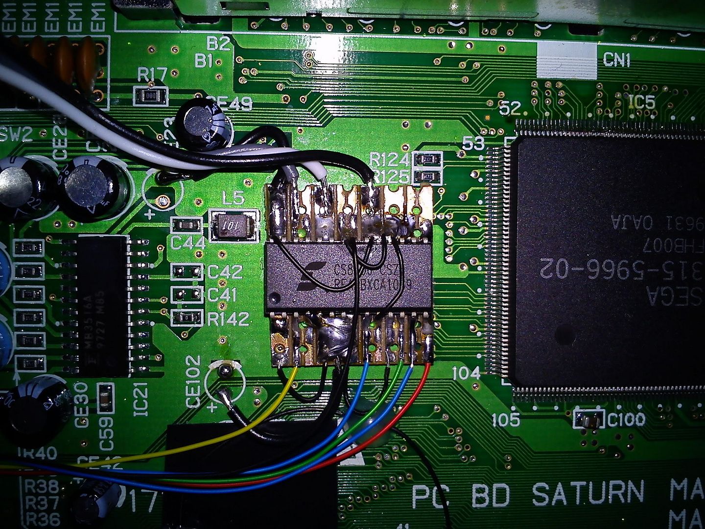
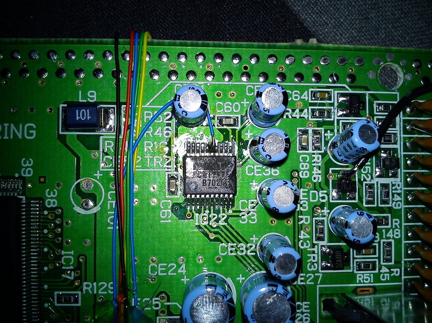
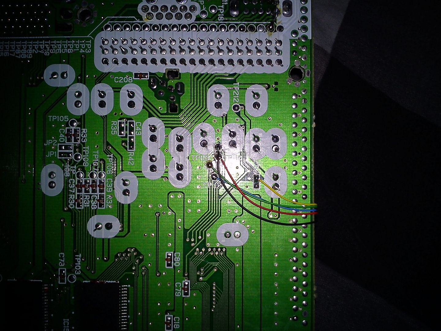
Here are pictures of the stripboard and MB soldering points:
Stripboard: http://i40.photobucket.com/albums/e236/ ... C00111.jpg
DAC: http://i40.photobucket.com/albums/e236/ ... C00112.jpg
C62 and TP-points: http://i40.photobucket.com/albums/e236/ ... C00108.jpg

I hope this will be useful, even those with different models might be able to work from this. Be sure though, to read the schematics for the DAC if yours is different, to find the proper Reset line-leg. There are also DAC's which requires their EMPH signal to be inverted for Pre-emphasis to work. This wasn't necessary on this model, so I'm probably not the one to ask, brendanraymond on the other hand seems to have a good understanding of this.

Any feedback on this would be highly appreciated :)
Post Reply